Products Condition Monitoring
Product Appliction
Condition Monitoring of rotating machines with
AV308-X
AV308-X is a new concept vibration measurement analysis module with
the size of a general three-axis accelerometer that aggregates MEMS
sensors, CPU, WiFi and USB interface.
Condition Monitoring is the continuous monitoring of rotating machines
during process conditions. This ensures the optimal use of machines.
Condition Monitoring supports predictive maintenance, which is more
efficient than preventive maintenance. Condition Monitoring provides
insight in performance, wear and mechanical risks of machines. This helps
to prevent unnecessary and unplanned downtime.
The AV308-X has 2Mbyte of memory and 240MHz of CPU inside. Using
this function, we want to show condition monitoring of rotating machines.
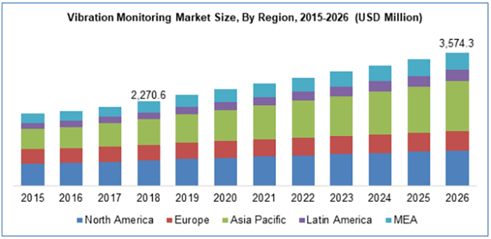
In the past, accelerometers were mainly used in large-scale equipment industries such as oil refinery, power plants, industrial pumps, and advanced machinery. Driven by increased automation, there is an increasing demand for small motors, conveyor systems or small systems such as machine tools that require better predictive maintenance. Machine downtime for these applications is an important consideration in terms of customer experience and profitability. In the past, accelerometers were mainly used for condition monitoring of high-end machines. However, with the digital industry innovation, the demand for large and small machinery is increasing. This application note introduces the application example of AV308-X in the condition monitoring of rotating machinery.
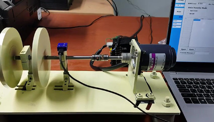
- Simple Divice for testing 'Condition Monitoring of Rotating Machinary'
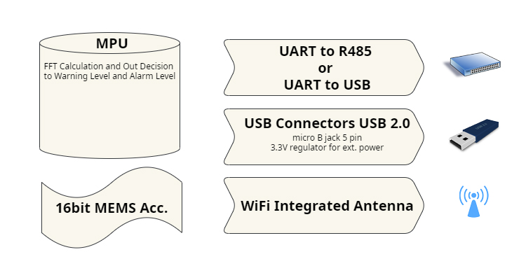
The acceleration sensor attached to AV308-X transmits the FFT
Spectrum using internal memory and the MPU's computing
ability, or receives the warning level, alarm level and fixed
frequency span from an external computer. calculates the
information transmitted from the computed spectrum and resends the results.
The following figure shows the simple structure of the accelerometer module.
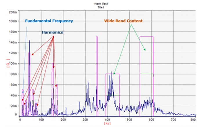
In order to transmit information such as warning level, alarm level, and fixed frequency span to the sensor, it is necessary to know the state of the rotary machine currently running. The above figure shows the spectrum received from the sensor as a graph and sets the information necessary for monitoring. Experts who are familiar with creating vibration monitoring software can freely configure programs by sending a spectrum and putting in the necessary elements, but end users who are not familiar with it will have to spend a lot of money and time creating monitoring software.
Transmit message protocol PC to sensor
| STX | ID | Mode | Size | Frequency/Order | Width | Warning | Alarm | Range | RPM level | ETX |
|---|---|---|---|---|---|---|---|---|---|---|
| 1byte | 3byte | 1byte | 2byte | 5byte | 5byte | 5byte | 5byte | 5byte | 5byte | 1byte |
| 0: Fixed Frequency Result 1: Order Result 2: Spectrum Out X: Axis Out; 0,1,2 Y: Axis Out; 3,4,5 Z: Axis Out ;6,7,8 |
1-20 | Repeat set size No. Freq./Order, width, warning and alarm not set. |
2,4,6,8,16 | x.xxx | ||||||
| Spectrum out mode: size zero Freq./Order, width, warning and alarm not set. |
||||||||||
| 0 x 0.2 | Use Ascii code '0-9' and | 0 x 0.3 | ||||||||
Transmit message protocol sensor to PC
| STX | ID | Data out | RPM | EXT |
|---|---|---|---|---|
| 1byte | 3byte | 5byte | 1byte | |
| Fixed Frequency result mode : Repeat set size No. 0: Good / 1:
warning / 2: alarm Order result mode : Repeat set size No. 0: Good / 1: warning / 2:alarm Spectrum out mode : 1024*2 (16bit integer) most significant byte first |
xx.xx | |||
| 0 x 0.2 | 0 x 0.3 |
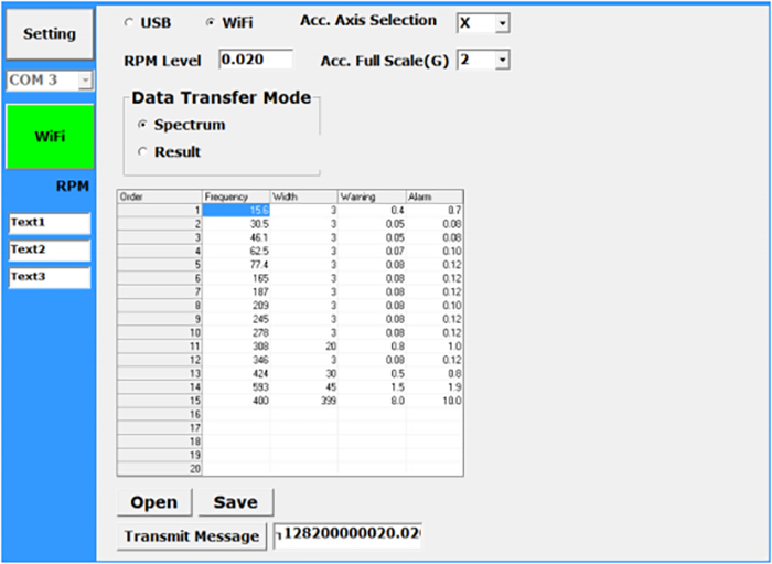
As shown in the picture above, the sensor is programmed to set up to 20 frequency, width, warning and alarm levels.
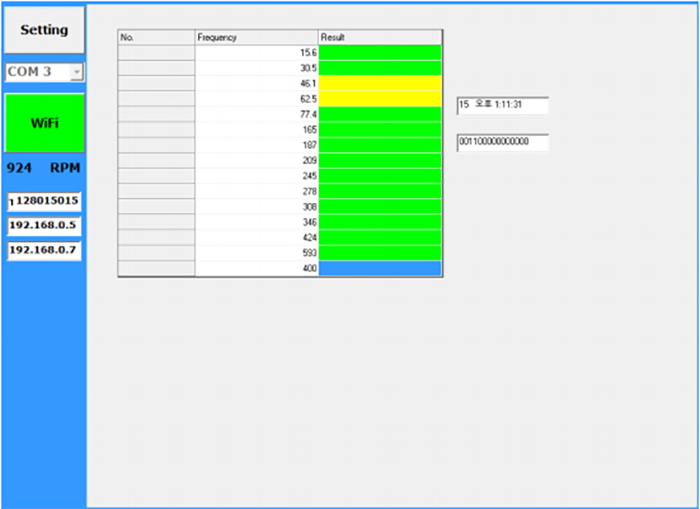
When a sensor receives a set protocol, it transmits the state of the rotating machinery using the internally calculated results. In the figure above, the normal state is marked green, the warning level is yellow, and the alarm level is red. Monitoring fixed frequency bands often does not fit on rotating machinery with varying RPMs. Order tracking is widely used for monitoring the rotating machinery with varying speed.
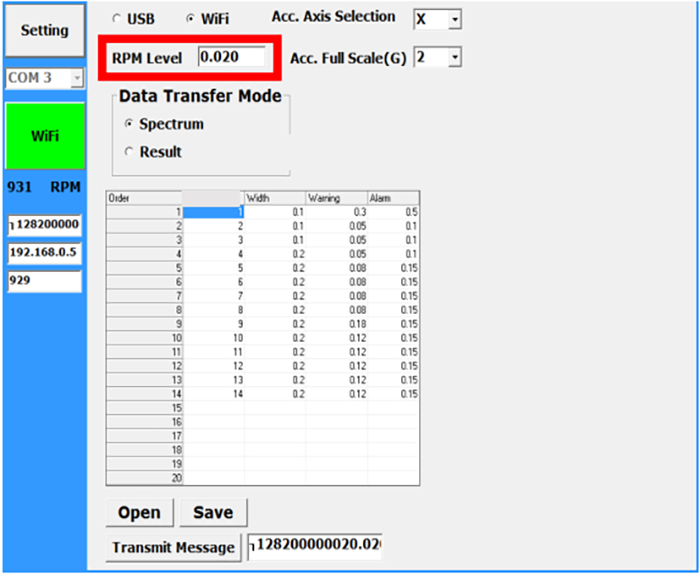
The fundamental frequency is detected in the spectrum analyzed by the sensor. The red frame in the figure above shows the level setting for detecting the fundamental frequency.
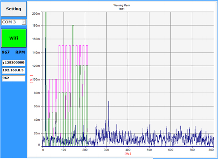
You can confirm by receiving the spectrum whether the set order information is set correctly.
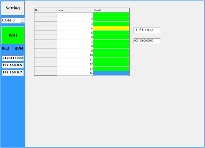
The above figure shows the result of receiving and processing the result determined by the sensor.

- Embedded 3-axis 16bit resolution MEMS Accelerometer
- WiFi direct
- Compact & light size for the improvement of measurement sensitivity (20*21*10mm)